10 minutes
Working with Arduinos
It all began with a cabinet I got from my parents. Being a bit of a hoarder in training, I have a mountain of computer parts and technical knick-knacks that I have yet to find a home for, and I thought that this cabinet could help me organize some of the clutter. It did, sort of. After doing a little decluttering, I realized that I really wanted to put lights all along the inside of it, but only have it power on when the door was open.
I was partly inspired by this video by a Youtube creator named ‘upir’, who created an Arduino-powered gear shift display using hall effect sensors. While a lot of what upir did in his video is very overkill for a project like this, his tips and tricks really helped over the course of the project.
V1
The first thing I did was create a mock-up of the project in the wokwi Arduino simulator. I used a switch connected to a potentiometer to simulate both an analog and digital input, which I figured I would replace with a BJT transistor and a photoresistor, two components I already had in hand and wouldn’t have to order.
After that, I hooked up a digital pin to an LED and set a threshold limit to check against. When the potentiometer was low, the LED was off; when it was high, the LED was on. Perfect. But I wanted more.
Because I didn’t want to use a Serial connection, I decided to add a 1602 display. Adding the display, and things to select on the display, required buttons for human interaction. I added 6 buttons: Up, Down, Left, Right, Enter, and Back. Once wired up, I created the items for the menu, including a passive mode, changing the limit settings, and enabling or disabling the backlight. Once everything worked in the simulator, I opened Kicad and began creating boards.
One thing I knew was that I wanted the project to be modular; if one part of the build needed to be rebuilt, I didn’t want to have to order the boards and resolder everything back together. So I ended up building 4 different boards that would theoretically work together using connectors. These boards were:
- A power supply
- The main board with the Arduino
- A board for the buttons
- A board for the sensor
Power Supply
I wanted my power supply to take in up to 19V and output 5V. There wasn’t really a reason for it, I had just seen this video from The Engineering Mindset and thought that it would be a good idea to potentially have a barrel jack provide power that the rest of the unit could use. So, I built the board according to the BOM the video above provided and asked myself what else could work well on that board.
I also put the 16x2 display on the board. Since it was the board that was furthest back, I felt that having the display be on the rear-most board would work better than having it in the middle or at the front with the buttons.
Finally, I put a USB port to plug the LEDs into, with a diode to prevent back feeding in case the user (I) put some sort of different USB device in.

Main Board
The main board with the microcontroller was probably the simplest of all the boards. It basically just housed the connections to all the rest of the boards, while also housing the primary Arduino microcontroller.

HMI
The Human-Machine Interface (HMI) board only had buttons. They were routed to a connector to talk to the main board. Not much to mention here.

Sensor Board
This board had a connector to talk to the Main Board, a small BJT transistor, and a photoresistor. The goal was for this board to be basically directly in contact with the cabinet door so that any movement would trigger it to tell the LED to power on. The cable would then route out of the cabinet to the main unit for communication.

The first revision of this unit was not super well-thought-out. Besides the silkscreen and component designators being all over the place, the only connectors I had on hand for the first revision were 2.5m JST connectors, so my LCD connections were two JST connectors that would then route around from the PSU to the Main Board in a large spaghetti mess of wires.
For my very first revision, I didn’t split out the sensor, so the sensor and BJT were on the PSU for this first version. To make matters worse, I couldn’t find an Arduino Nano, so I purchased an Arduino Micro instead, forcing me to update my code and my Main Board to account for the different microcontroller.
The button board was probably the best out of all of them, but even then, when I stacked the boards how I would want them to go, I found that the width was very uneven, and it would really stand out if I didn’t make them all the same width.

V2
Almost mercifully, the first revision didn’t power on when the parts were installed and power was plugged in. I’m not entirely sure why it didn’t work, but that was fine because I needed to remake all the boards anyway.
On the Power Supply, I added a power switch; changed the JST connectors to a 2x5 header; added a potentiometer for the display contrast; and made the silkscreen and reference designators all face the same direction. I also used it as the base for the other boards.

The Main Board was changed to fit the width of the PSU, and had the JST connections updated to the headers for talking between the PSU and the HMI. Only the Sensor Board connection remained a JST.

The button board gained an LED for power verification, and was also changed to fit the width of the rest of the unit.

V3
The second revision also didn’t work. While the boards stacked together much better, one of my primary issues was dealing with the Arduino. Arduinos are expensive, something like $30 USD for each Arduino Micro, and I really didn’t want to buy a new one for each revision. While yes, my boards are modular, there was also a very real possibility that I might to redo the Main Board again, and I didn’t want to solder such an expensive microcontroller to the board.
To get around this, I tried to install pin sockets into the board, which brought on a new problem: the Arduino was too tall, and would push the button board away, making poor connection. I tried to install the pin headers from the Arduino in a weird way so that there was about 1mm more of clearance, but too much solder was on the leads, causing a poor connection. I can still use the Arduino Micro for other projects, but I had likely ruined it for this one.
Luckily, Youtube introduced me to this video by Abe’s Projects, where Abe created a digital dice roller using a Raspberry Pi Pico, a custom PCB, and a display. Again, all stuff that is a lot more than what this project is trying to be, but made me look into the Pi Pico and made me realize that the $8 price tag is a much easier pill to swallow than the $30 for the Arduino.
I updated my simulation in Wokwi to account for the Pi Pico and verified that everything worked before converting my Main Board from the Arduino to the Pi Pico. I also made some minor changes to the PSU and Sensor boards, as in my testing, I realized I likely needed a 4-pin JST rather than a 3-pin so that I could read the GND value.


V4
About this time, I was wanting to take a break, so I put the project on the shelf and never built V3. Over the next several months, I did a several other things. I have a hobby list a mile long, and so I can bounce from idea to idea, partly to give me a break, but also to keep me from getting too burnt out on any one specific hobby.
I had picked up a few Waveshare RP2040 minis after hearing about an open source Xbox modchip called ModXO. At first, I thought about building some of my own and selling them online, but realized the overhead would have just been way too high, so I dropped the idea. However, I still had these RP2040s just lying around, doing nothing.
I was playing with an ESP32-C3 I had purchased for $3 when I realized that, if I cut the scope of my project by a lot, I could have the basic light controller that would likely just work. So I cut the display, buttons, and PSU, keeping only the main board and the sensor board.
I had to figure out if I wanted to sacrifice the RP2040–with its 17 IO pins–or the ESP32-C3–with its Wifi and Bluetooth capabilities–for this project, and eventually settled on the RP2040. Partly because I felt like the ESP32-C3 could be used better elsewhere, but also because I might be able to add my original HMI idea with all the extra pins in a future revision.
I completely redesigned the Main Board, forgoing the PSU idea and will simply be using a standard 5V USB-C charger since they come with everything nowadays. Beside the USB-C power plug, there is now only a connection to the sensor board and another to the LEDs.

The sensor board was updated to use a hall effect sensor instead of a photoresistor. I had wanted to do this upgrade for a long time, but didn’t want to spend the money until I knew the project would work. I updated the code, using some ideas from upir’s video above, and confirmed that everything works with the RP2040, wires, and a testing breadboard.
Maybe in the future there will be a V5 with a display, but for now I’m happy with what I have. This project has made me learn so much, and gave me a great appreciation for hardware engineers. Even though I’m an electronics assembler in my day job–and have been for 8 years!–putting something together that you built yourself is a completely different feeling, and when things are difficult to build, you only have yourself to blame.
This definitely won’t be the last project I make. Doing one project like this is almost addicting, and there are always more, hidden just around the corner. Small itches that you need to scratch, or even weird things like these cabinet lights that really won’t make a huge difference in the grand scheme of things. And hey, it’s fun.
Update April 2025
The relay ended up not getting enough voltage to fully trigger, and so the above revision needed yet another revision. I added a small BJT transistor that would then send the full 5V to the relay trigger once the microcontroller pin was triggered high. Ironically, the same BJT Transistor essentially removes the need for the relay, but I like the audible clicky feedback better than the silence.
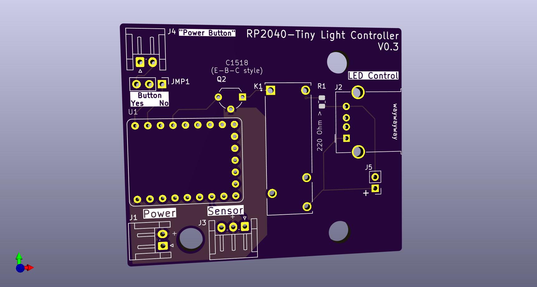
I also moved the JST Power and sensor board connections to the bottom, removing the “Power Only” UBC-C port due to essentially being unnecessary for my particular use-case. In its place, I added another JST connection for a momentary pushbotton in order to have a soft power button. I also added a switch to detect if a button is/will be connected and automatically power the board up regardless.
Part of me would like to slightly change the board shape and add a few LEDs for more feedback, but with the recent Tariff news, I am more than happy with my existing working system.